MEDW 55V 3A Stepper Driver - Construction
Assembly of the stepper driver is relatively simple with quite a small list of components to install. Use the kitting sheet to help identify which component goes into which location on the board. By inserting the lower profile components first, the assembly process can be assisted by using a block of foam to hold them in place as you assemble. A PCB assembly frame makes things even easier, but is not worth the investment if one is only assembling a few boards.
 Fit resistors and the Zener diode.
 Add the small capacitors and the resistor network.
 Add the header strips and sockets.
 Fit the opto-isolators, transistor, and the big capaitors.
 Loosly fit the driver I'C's pushing them through as little as possible while still ensuring all pins are ehrough th board.
 Bolt the I.C.s to the heatsink with an M3 bolt and shakeproof washer. ( Heatsink compound can be used, but normally cotact to the heat sink is fine without it ).
 Bolt the heatsink to the board.
 Solder the driver I.C.s to the board, making sure that the pins are still protruding thrugh the board.
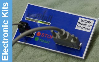
The board is now ready for testing, and that requires connecting it to a breakout board which can provide step and direction signals. The connections to the MEDW0010 breakout board are described here.


