From the Shop: Digital Scales - "The YADRO-Files" : Part 1
The ALDI-Present:ALDI is one of the bigger food-discounters in Germany. Yes, sometimes they also sell digital scales, shoes, vacuum cleaners and whatever. Recently (beginning of september 2005) Aldi offered a digital scale. The price tag was ¤ 9.99 (about USD 12). I could not resist, because I also hoped that this scale has a digital output. I took 4 of them and opened them and found what I hoped to find. A digital interface.
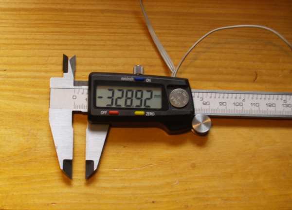
Now here it is. Cables already connected, battery cover missing and -after inserting the battery- a bit confused display. But you can interpret it as a hint. There is more in it than it seems. Quality? Oh, yes. There is quality, a bit of. No good workmanship, sharp corners etc. but it is precise: I checked it with two gauge blocks with 25mm and 50mm. Both times the scale was 0,00mm off. Better than I hoped. |
|
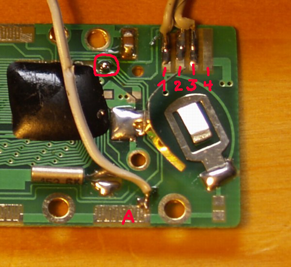
The PCB:After opening the case and disassembling the pcb there where 4 highly suspicious pads. They -after connecting a scope to them- revealed to be the digital interface.But even more. There is a pad that looks like the 3 other pads that serve for the push buttons.
What is marked 1…4 is the digital interface connector. "A" is the additional pad for the switch. In the circle is a little secret. Be patient, I'll come back. All push buttons are pulling the corresponding pads high (H, plus of battery) and that's what I tried with the mystery pad "A". It didn't work. Later I decided that it must make some sense, so I traced the pcd to see where it is connected to. It was not connected. It ended under the artful tinn pickle I made (and that is marked with the circle). The trace ended in a pad and right beside that pad was another pad that cried for connecting both. I did as requested and the scale answered with new features. The push button that serves the pad "A" will -from now on- be called the phantom button. It doesn't seem necessary to put a resistor in the trace. All the other switch pads don't have them too. If you want to be on the save side, use 100 … 500 Ohm.
Under the sticker:Note: That's how it looks if you peel off the sticker (with the ruler's numbers printed on). On the left is the calipers body (a part of it) with the sticker removed. To the right is the backside of the PCB. Sizes if you look at the enlarged picture. The pad on the PCB that is 30.5mm wide receives the signals. Those signals are coming from the 56 pads underneath. I have lent me a HP 54645D. A wonderful mixed signal scope. 100MHz 2 channel analog + 16 channel digital. Quite old (mfg-date unknown) with a centronics interface that took 5 minutes to print one page. Then I scanned the pages. I had so much joy using it! Thanks a lot to the guys at eubus! Here is a picture showing the signal (analog channel on top is the receiver pad). Here is a detail of the above screen dump (the part marked "see#2") (0.8 MB!) Here are 3 parts of the digital signals strechted and timing handwritten into it: Digital part#1, part#2, part#3 C3
is connected to the leftmost sender pad, C2 to the second, C1 ->
3rd, C0 -> 4th, C7-> 5th, C6 -> 6th, C5 -> 7th, C4 ->
8th. Here is a drawing how the coupler-pcb and the slide-pcb work together: I name the parts:
Part 5…7 are on the coupler-PCB that is glued into a recess of the body (4). Part 5 doesn't seem to have some function. Drawing is to scale where necessary (especialy the relation of 3, 6, 7)
The modes of the "pimped scale":
The interface:Side note: You can only switch off the display, the digital interface stays active. Attention: Ground planes and the scale itself are connected to battery +. But this should not concern you for now. The Pins:
Nominal battery voltage is 1.55 V; L is < 0.2V; H is > 1.3V
The signal, or do the Chinese read from right to left?
The
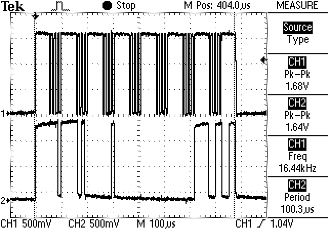
signal. Upper channel is clock, lower channel is data. A complete
datagram is about 780us long. Every packet has 4 bits (BCD). The last
packed transports additional information The whole datagram consists of
7 pakets. So you can transmit 6 digits that would result in a maximum
range of 9999.99mm The LCD is only good for 999.99mm, but the IC could
handle more. If you only cut the scales and put them in a row …
Two
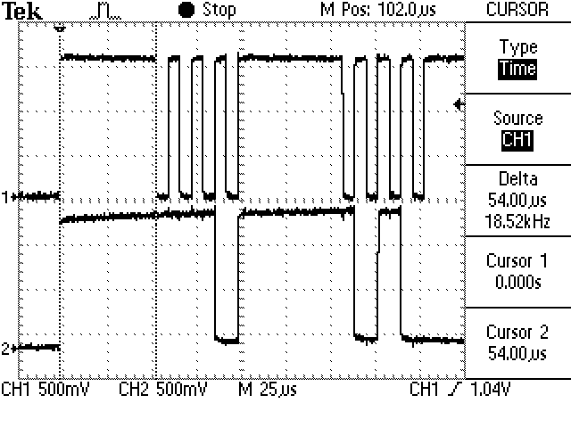
packets (the first two) at a closer look. Every packet has a lead in of
54us H. Following that are 4 clocks that signal the bits. Reading takes
place at the falling edge of the clock. In the first paket is the
lowest (LSB first) number. If the display reads 123.45mm, the packets
read 5, then 4, then 3, etc.
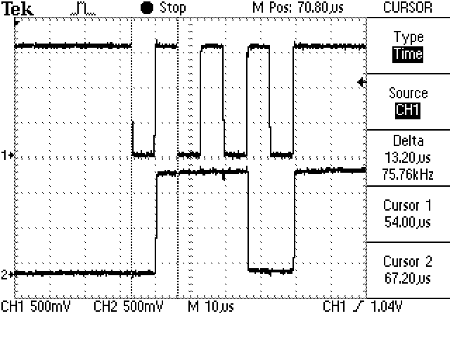
A single packet with a closer look at the timing. Reading is always at the falling edge! The last packet: The last packet does not transmit numbers, but additional information They are in detail (LSB first):
|
 click to enlarge
 click to enlarge (1.2 MB!)
 click to enlarge