From the Shop: Digital Scales - "The YADRO-Files" : Part 2
When size counts:OK, the caliper from part one is nice, but it won't serve that much on a mill or a lathe that is not just a toy. We'd like to have bigger and better dedicated linear scales. You know that they are available and you also know that they are more expensive than the bargain I described in part one. But they won't make a vacuum in your wallet. The ones I bought costed about ¤ 45.- for 150mm, the 300mm costed ¤ 65.- So we buy these and see what we can do with them.
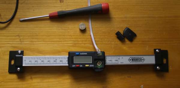
Here is my 150mm linear scale, just unpacked and the wires already know connected. Well, you guessed it: The connector looks exactly the same like the one of part 1. But even worse (or better?) the PCB looks quite familiar too.
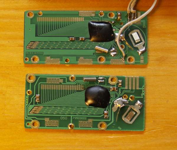
The upper PCB is the one of the caliper, the lower one is the linear scale's. The linear scale has less buttons (you won't miss them, as you will see later), the X-tal has moved and some resistors. Yes, I tried to see whether I can convince the PCB from part 1 to behave like the one from part 2 (the one you are just reading), but I didn't see a way. But also, no need to worry! |
|
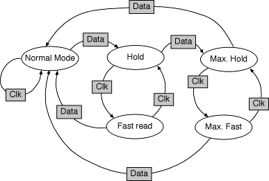
The modes:The modes, and how they are switched, is best described by a state diagram:
Gray rectangular boxes are events, round boxes are states. The possible events are:
There are further events like OFF/ON or inch/mm, but they are either obvious or change the mode in any state. The possible states are:
Note, that you can find valid combinations in the state diagram.
The interface:The connectors are exactly the same as with the caliper, so I will just remind you: Digital output pads from left to right: Pin 1: Battery - Note, that the Chinese were kind enough to confuse Data and Clock in their leaflet they provided. In the German paper, they claimed an RS232 interface, that's wrong too. Side note: You can only switch off the display, the digital interface stays active. Attention: Ground planes and the scale itself are connected to battery +. But this should not concern you for now.
Nominal battery voltage is 1.55 V; L is < 0.2V; H is > 1.3V
The signal, or do the Chinese read from right to left?
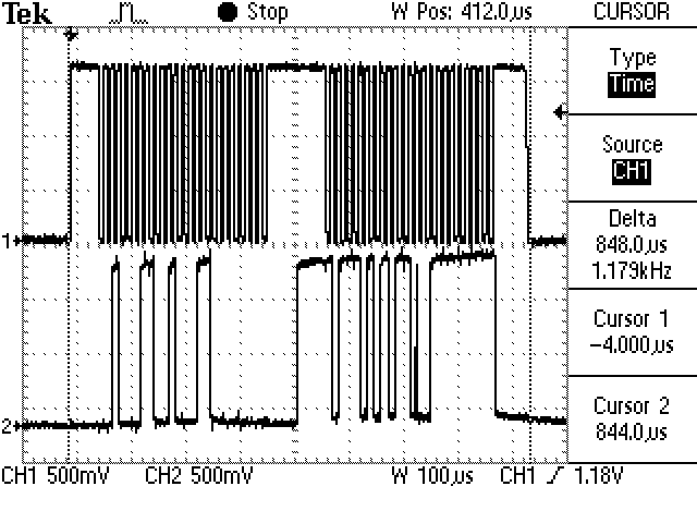
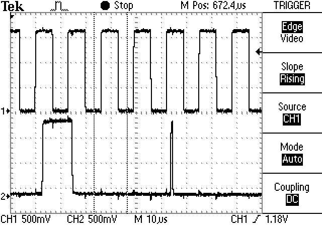
The signal. Upper channel is clock, lower channel is data. A complete datagram is about 850us long. There are 2 packets. Every packet has 24 bits. The first packet transmits an absolute position, but there is no absolute info on the scale itself. It is quite worthless, because what the scale thinks that his absolute position is, changes whenever the power is removed. The second packet is the relative position in respect of where you pressed zero.
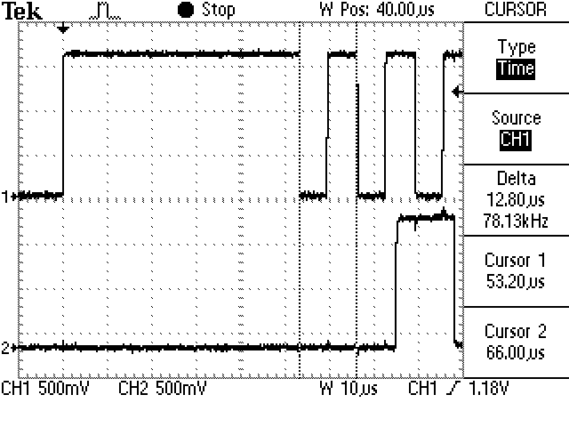
Part of the first packet at a closer look. There is a lead in that is about 53us long. Following that are 23 pulses that have a cycle time of 13us. As with the caliper of part 1, data is read at the falling edge. Bits are transferred LSB first! Also, data is 2's complement.
If you think it is wise to read when the clock is H, here is a shot that shows a glitch that hopefully will stop you from making that error. There is no information transmitted about the state the linear scale is in. No units, no hold, nothing. The data is not directly a representation of the display. To interpret the data, you have to scale it. Every inch is divided into 20480 steps. Or every mm has 806.299 steps. Wow! This would give a resolution of 0.00005 inch, or 0.0012mm! No, not exactly. The last bits have jitter. Maybe with averaging, the results gets stable, I will see later. As far as I can tell now, the jitter is about +/-5 units.
|