From the Shop: Digital Scales - "The YADRO-Files" : Part 3
<back< >next>
Wouldn't it be nice…
| The following text might leave some or many questions.It's you who has to ask. Then it's me who will fill the gaps. |
The idea, the concept, the goal, the result:
When
I started the whole YADRO-thing, my idea was to connect the digital
scales to a computer. As the signals were not in a form a normal PC
would accept and have the real-time capabilities to process them, the
solution was obvious: Build a uC (that's micro-controller) board that
connects to the scales on one side, and on the other side to a PC. To
make things as flexible as possible, I decided to use RS232 for
communications. Also, the uC should be able to connect to 4 scales and
handle the two types described before. It also should supply the power
for the scales and live well in an electrically noisy environment. The
last point lead to an opto-coupled RS232.
Also, the
software in the interface should help you in connecting and debugging
your scales. It should also make as little assumptions about what is
exactly connected. The reason was, that it is much easier to configure
software on the PC then in the interface. Those uC have only about
2kBytes of ROM, 128 Bytes of RAM. Not that much, but where they are
great is their speed. So the software in the interface is just a layer
of communication and data collection and not a layer of interpretation.
The firmware:
I'll
start describing the software (or firmware) to show you how powerful
(but simple) it is. As said before, the interface communicates via
RS232. The communication speed is 19200 Baud (I'll make that
configurable). Currently, there is no protocol like XON/XOFF or even a
hardware handshake. The hardware-handshake will never be implemented,
but probably a XON/XOFF. But also, I currently see no need for that.
(Update: The communication is really stable, you can disconnect the
serial cable without any hickups)
If you connect the
YADRO-interface to your PC, start a terminal program (having set up the
baud-rate properly) and then power up the YADRO-interface, you will be
welcomed by:
*** Welcome to YADRO-land! ***
(c) 2005 Nick Mueller // www.motor-manufaktur.de
When this happens, your interface is (at least somehow) running and the connection to the PC is OK.
I have assembled a very simple terminal program (Y-TERM.EXE) for you that connects to COM1 and sets the baud rate to 19200Bd. Nothing valuable, but it works under DOS.
Now,
you can communicate with the interface. To communicate means, that you
type a character at the console that the interface receives and
interprets. There is no echo, but a response if the command is
understood. You don't have to terminate commands with a CR or so.
YADRO's RS232 characteristics:
- 19200 baud
- 8 bit
- 1 stop bit
- no handshake (neither XON/XOFF, nor RTS/CTS)
Note, that commands are case-sensitive! All responses from the controller are terminated by a CR/LF
I'll describe the commands and responses in a somehow logical sequence:
command
(Typed in a the console) |
action
(happening inside the controller) |
response
(from the controller) |
| v |
version
Displays version of firmware |
YADRO-DROINT v0.2c
|
d0
d1
d2
d3 |
Debug/display device #0… device #3 verbose information.
Valid range is 0..3. If you are out of range, you'll get a warning.
A
"d"-command prepares the interface for reading from a (connected)
device. If you start the YADRO for the very first time, you need to do
at least a "da" or a "d0" etc. for each digital scale connected. If you
don't do that, you will get error-warnings when trying to read from
that port.
This command may take up to 2 seconds. It
will even take longer if you connect some low frequency generating
device to it. But you don't. |
If nothing is connected to the port:
Checking device #0...
Clock :stuck H
Data  :stuck H
If something is connected:
Checking device #0...
Clock : Signal
Data  : Signal
If that something is recognized:
Checking device #0...
Clock : Signal
Data  : Signal
Device: 7BCDs ('B')
or
Checking device #0...
Clock : Signal
Data  : Signal
Device: 2*24bits ('L')
|
| da |
Does a "d0", "d1", "d2", "d3" for your convenience in one block. |
see d0…d3 |
| dw |
Writes
the information gathered by a "da" or "d0"…"d3" command into the
interfaces non volatile memory (EEPROM). If you switch off and back on
again, that information is read back automatically, so you don't have
to go through a "da" sequence every time you power the YADRO-interface
up. |
OK
|
| dr |
dr
is the inverse of dw. It reads the configuration from the EEPROM. You
normaly don't need that command, as YADRO reads that information after
each reset/power up. But it helped me to find a nasty bug. So I'll
leave it in there.
The numbers you get are 8bit hex and
representing the number of bits the scale connected to the ports (from
left to right / from dev0 to dev3) is reading. 00 means nothing
connected. A 31 would be a type "L" scale. |
31313100 OK
|
r0
r1
r2
r3 |
Read from device #0…#3. You have to have set up the interface at least once with a "da" command.
The output is in hex, terminated with a CR. The bit order is exactly
the same as it was received. There is no interpretation at all.
After the devive#, there is a character indicating the type of device connected. It is either a "B" or a "L" |
DRO#0B:0x00112233
or
DRO#0L:0x0011223344
|
s0
s1
s2
s3 |
Sample
device 10 times. This is a burst read from one device. E.g. like
calling 10 times the "r" command very fast. You can use this to find
out (during setting up) whether your digital scale can be switched to
fast mode. It also might help in averaging the reading of that port on
the PC side. |
10 times like a r0, r1, r2, r3 |
| a |
Active
mode. In this mode, all ports are read in an infinite loop and,
whenever a port changes it's value, it is sent. When no reading
changes, no data is sent at all |
OK
Then: see r0, r1, r2, r3 |
| p |
Passive mode. Just terminates the active mode. The passive mode (or "polling mode") is the mode when the YADRO is powered up.
To get readings in that mode, you have to ask (to poll) values with "r0"…"r3" or with "s0"…"s3" |
OK
|
c0C
c1C
c2C
c3C |
Config
port, by pulling Clock high. This command pulls the Clock line of the
digital scale to high (1.55V) for 1 second. It helps in switching
modes. See the previous pages and the description for details. Note that the second "C" is capital. |
OK
|
c0D
c1D
c2D
c3D |
Config
port, by pulling Data high. This command pulls the Data line of the
digital scale to high (1.55V) for 1 second. It helps in switching
modes. See the previous pages and the description for details. Note that the "D" is capital! |
OK
|
| R |
Resets the interface. This is a software-reset, and the command might be quite useless. But it exists. |
The welcome text |
Be
friendly to your interface! Do not flood with commands, but wait 'till
you get a response. If you do send a command before you got a response,
the command will simply be lost. The controller only buffers one
complete command and empties that buffer after the command is processed. If you send unrecognized commands, they will simply be purged without any comment.
The hardware:
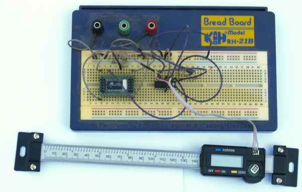
The
picture on top of this page is a shot from the very first
design-verification stage. It helped me in developing the software. I
used a ready made uC module with an RS232 interface. As programming
language, I used assembler. No C, no Basic.
Here is the schematic as a screenshot. Just if you want to have a short glance at it.
When
you look back to the description of the scales, you will see, that they
work with 1.55V and communicate through 2 pins. As the voltage is to
low for a uC to work with properly (there are no uCs that have a supply
voltage of 1.6V), the levels of Clock and Data have to be scaled. This
is done by OpAmps (IC3, IC4) that work as comparators. As Clock and
Data also have to be pulled high, there must be a means for switching
1.55V to the pins. This is done by a 8:1 analog switch (IC5). The
supply voltage for the digital scales is supplied by a voltage
regulator (IC2). All the processing is done by an ATMEL ATtiny2313
(IC6).
The communication side is -unfortunately- a bit more
complicated than it might have been. The reason is, that the scale's
metal parts are connected to the batteries+. This results in difference
in potentials and destructive short circuits if the interfaces ground
gets a connection via your PC. So the RS232 interface had to be
isolated by the two opto couplers (OK1, OK2). A proper connection to
RS232 is done by the old and trustworthy MAX232 (here a MAX 3232N,
IC1). Due to the isolation, IC1+OK1+OK2 need a potential free power
that is obtained by the DC/DC-converter (DC1).
Building the real thing
In the meantime, I got a PCB. Lots of thanks goes to Oliver Betz (oliverbetz.de) who made a professional layout for me (after he has seen my attempt).
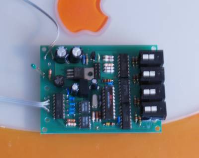
You can download the complete project (schematics and PCB) here. This doesn't mean it's in the public domain. Read the legalese on the end of this page.
To read the files, you need EAGLE. You get a free non-commercial version here.
For placing the parts, I made a shot (click to enlarge):
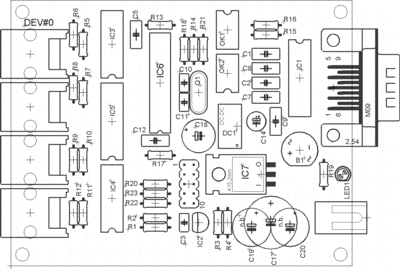
BOM
Due to editing, there are gaps in part numbering of the Cs (C4, C6, C13, C15, C16 missing).
| Part# |
Spec. |
Comment |
| Capacitors |
| C1, C2, C5, C7, C8, C9, C12 |
100n |
ceramic |
| C3 |
10n |
ceramic |
| C10, C11 |
22p |
ceramic |
| C14 |
10u |
electrolytic, 6V |
| C17 (or C19 + C20) |
1000u |
electrolytic, 33V, you can split C17 to C19/C20 with 470u |
| C18 |
25u |
electrolytic, 6V |
| not drawn |
1u |
tantal, 6V, going in each digital scale |
| Resistors |
| R1, R2 |
1k |
metal film, 1% |
| R3 |
56 |
metal film, 1% |
| R4 |
220 |
metal film, 1% |
| R5…R12 |
100 |
|
| R13 |
100k |
you can use 10k, if you want |
| R14, R15 |
330 |
|
| R16, R20..R23 |
3k9 |
|
| R17, R18 |
10k |
|
| R19 |
470 |
|
| Diodes |
| B1 |
B40C800 |
bridge rectifier; minimum 20Volts, 200mA; a B250C800 is OK |
| LED1 |
-- |
power on LED; 2mA type; any color; can be left out |
| Integrated Circuits |
| IC1 |
MAX232N (TI) or MAX232ACPE (Maxim) |
available from Maxim or TI. It must be for 100n caps |
| IC2 |
LM317LZ |
TO92 case |
| IC3, IC4 |
TLC274P (DIL case) |
speed critical; don't use a replacement by guessing |
| IC5 |
CD4051N (DIL case) |
can be 4051B to |
| IC6 |
Atmel ATtiny2313-20PI |
a Atmel 90S2313 does not work |
| IC7 |
uA78S05 |
1.5 Amps (200mA would be enough) |
| OK1, OK2 |
HCPL4502 or 6N136 |
|
| Misc |
| Q1 |
20MHz (HC18 case) |
can be the higher case to |
| DC1 |
5V/5V DC/DC |
5v-5v DC/DC converter; isolated; 0.5W; output unregulated +/-10% SIM4-case |
| X1 |
low voltage power supply connector, female |
|
| X2 |
9 pin D-sub male |
get a PCB mounting or a front mounting one |
| DEV#0…DEV#3 |
4/4 RJ11 |
4 pin 4pins connected; "telephone type connectors" AMP |
| SV1 |
10 pin DIL-head, male |
might be left out depending on your programming means. |
| not drawn |
power supply 9…15V AC, 200mA min. |
|
| not drawn |
null-modem cable 9 pin female/female |
length as required |
All Rs are 1/4Watt, 10%, ElCheapos. Except R1, R2, R3 and R4 that should be 1% metal film.
Voltages of electrolytic caps can be higher as long as they fit onto the PCB.
If someone is willing to put a list of order# (for local dealers) together, I'll be glad to add it.
I used no sockets for the ICs. And, according to Murphy's law, the uC went kaputt during the first programming. YMMV.
Modifications:
- If you want, you can use a regulated 5V DC-supply and leave out C17, C19, C20, IC7, B1 (and connect the 5V at the appropriate places of IC7).
- If
you can't get the DC1, you can use two split supplies. Don't connect
the serial part around the MAX232 to Vcc and GND of the rest of the
circuit!
Scratch building:
If you can't etch a PCB or want a scratch build YADRO-DROINT, here is how I made my proptotype:
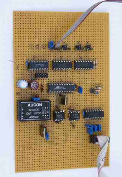
Identifying the parts:
- Top row: (with the cable) Connectors for the digital scales
- second row: IC5, IC3, IC4
- between second and third row: ISP-connector for programming the uC
- third row: Input buffering capacitor(s), IC6, IC2 crowded with 3 resistors
- forth row: DC/DC converter, OK1, OK2, IC1
Before you try to scratch build the interface, let me tell you my experiences and give you some advice.
- Power
is either a regulated wall plug supply with 5V (and about 500mA) or an
unregulated DC with 8 to 15V. If you use an unregulated, you need IC7
and C17.
- Use simple experimenting PCB. Place the
parts (more or less) like I did. I only urge you to place the IC2 in
the upper row (on the photo) near IC6/IC3/IC4. If you don't, the 1.55V
will catch to much noise and the digital scales will produce unstable
readings. Connect C3/C4 close to IC2's pin 2.
- Check the output voltage of IC2. It
should be 1.5 … 1.65Volts. If you have more, decrease R3 (by connecting
something like 1k parallel to R3). If you have below 1.5V, decrease R4.
- Do not route the connections with 1.55V close to Vcc or digital signals. You will get spikes that produce an unstable reading.
- Try to isolate the DC/DC-converter from Vcc as good as possible. Connect C13 and C18 directly to the converter's input.
- If you can't get a 5V/5V DC/DC-converter, you can use one with a higher output-voltage (as I did) and put a 7805 behind it.
- If you can't get a DC/DC-converter at all, you need two separate power supplies!
- Be aware, that the RS232-section has different ground and Vcc. Do not connect to the rest's Gnd!
- Solder a 10nF (ceramic) and a 1uF (Tantalum) capacitor into the digital scale's battery compartment.
- If
you have a closer look at the photo, you will see that I made some
surgery on the two opto-couplers. It was my fault, I bought dual OKs
that only work after some mods.
- After having made all connections, and
before inserting any ICs, connect to power and check voltages (Gnd and
Vcc at all ICs), especially the 1.55V. You don't want to ruin your
scales.
- It is wise (but not really necessary) to
connect unused Clk and Dta-pins of the device connectors (DEV#0..DEV#3)
with 10k to ground.
All capacitors are ceramic for values
below and including 100nF. Capacitors above are polarized electrolytic.
C4 and the 1uF caps in the digital scales are tantalum (others won't
fit in anyhow).
And the software?
Before
you can download the firmware into the controller, you need a circuit
to program the ATMEL. It is programmed in the board -with power connected- via the ISP-connector.
After you have the necessary programming interface, download the current version of the controller's firmware here, load it into the programmer's software and flash it into the YADRO-interface. Current version is V0.2c.
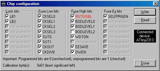
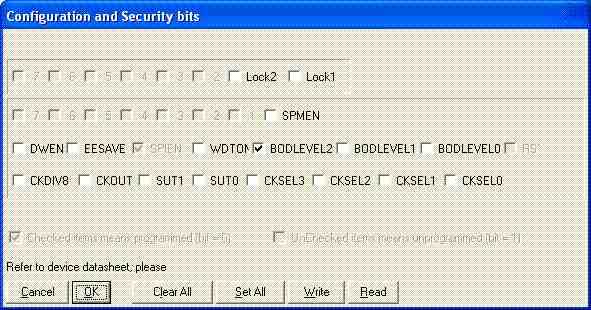
Do not forget to set the configuration bits of the uC when programming it.
DWEN, EESAVE, WDTON, BODLEVEL0, BODLEVEL1, CKDIV8, CKOUT, SUT0, SUT1,
CKSEL0, CKSEL1, CKSEL2 have to be unchecked. Only exception is BODLEVEL2 that has to be checked.
See the screenshot, if checking/unchecking/programm/set/whatever confuses me like it does you.
If
you forget to set BODLEVEL2, chances are that you are loosing the
configuration after disconnecting the power. BODLEVEL is brown out
detection, if you care.
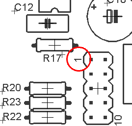
Look twice where pin 1 of the ISP-interface is!
Programming with TwinAVR:
This is the simples programming-interface
(called TwinAVR) you can imagine. If you decide to use that one (I
haven't, but got good feedback), you can build a simpler interface
(compared to the one shown at the TwinAVR's page) that connects to the
10 pin head (SV1):
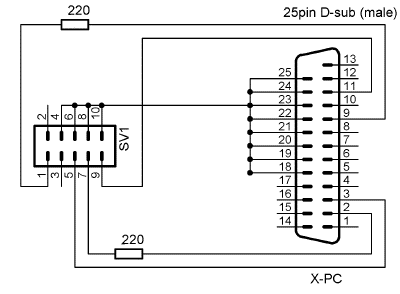
The
"X-PC" connector goes to your PCs Centronics printer port. You just
need 2 Rs with 220 Ohms. While programming you have to connect the
power supply to the YADRO-DROINT.
Set the configuration and security bits this way:
Programming with PonyProg:
You can download a plan for a ISP-interface and software for programming the uC here.
This solution is more complicated but saver. If you intend to do your
own projects with ATMELs, I would suggest using this one (or something
similar). ISP-compatible interfaces are available at many dealers for
around $10.
Set the configuration and security bits this way:
One more thing…
The software and the circuit is free -if and only if- you use it for your own private purposes. Commercial use is not allowed.
Requests for a commercial version/license are welcome.
<back< >next>
|