
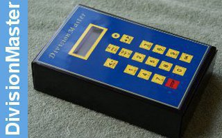
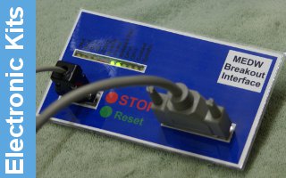


MEDW0003AssemblyInstruction
We have tidied up the printed circuit board to include the connections for the reset switch which is used with the Max/Min version of the software. The hole sizes have been tidied up, and the connection pins for the remote sensor. The board is essentially the same as the original article, but using components that match the rest of the MEDW kit projects.
For the larger display, please refer to the additional notes on that upgrade.

The pcb is single sided, so four links are required to connect pins from the PIC to the correct layout on the display connector. The long leads of the two 100n capacitors can be used for this. Leads from the resistors should be saved as well to use later when linking to the actual display. ( You will need the ones from the sensor board as well ! )

Resistor 8 can be omitted if the reset option is not being used. The 8 digit display and the simple 16 by 2 display software does not need the reset switch which is only used with the max/min 16 by 2 display version.

The crystal and small capacitors can then be fitted, laying the crystal tight against the board. If the display is likely to be subject to vibration while it use, it would be useful to secure the crystal with double sided tape to prevent the joints fracturing.

The remaining discrete components can now be fitted. The legs of the voltage regulator are bent tight to the molding allowing the hole to line up with the mounting hole in the pcb. A small bolt and nut ( not supplied ) should be used if the vibration problem might exist.

The PIC processor is mounted in a socket to allow it's removal for reprogramming if required.

The wiring to the board will depend on how the display is going to be used. For a cased unit it may be useful to fit a connector for the power and sensor, and if needed the reset buton is fixed to a flying lead. The unit can be powered by a 9V battery, in which case a switch would be fitted to switch off when not in use, or a DC main supply could be wired direct to the board. ( Take care to ensure that the +ve connection is to the right of the power connector ).

If you plan to wire the sensor cable direct to the board see the details in the sensor assembly which shows how to terminate the screened cable to the board. Since the connections to a stereo jack socket are short, there is no need to use screened cable inside the box.

One little drop off on the board tidy up was forgetting to add a hole below the contrast pot to allow adjustment once the display is mounted. Setting the contrast pot to the 3 o'clock position will give a reasonable contrast, but you will need to unscrew the display and hinge it up if you find that you need to adjust it.

A 12mm spacer is required between display and drive pcb. The 5mm MF spacer will lift the display to just behind the lid of the recomended box.

Once assembled mechanically, ten wire links are needed between the display and pcb. Note that there are no links needed for pins 7 to 10, which are not connected to the PIC. The display is run in 'nibble mode' so only four of the eight data pins are required.
Tacho Sensor
Given the amount of noise generated by some motors, it is a good idea to use screened cable to connect the sensor to the display. Since the sensor is using optical devices, there is no need to connect the sensor board earth to any metalwork. Simply mechanically mount it as appropriate.

An additional hole has been added to the cable connector, to allow easy securing of the cable screen. The two signal wires are stripped, tinned and fitted to the outer two holes.

Then a wire link is looped over the screen, removing the need to try and make the screen small enough to fit through a hole.

The screen is then soldered top side, and the tail removed. This ensures that any strain is against the cable screen and not the signal wires.

The resistors can then be fitted, along with the sensor. Note the position of the small chamfer on the reflective sensor.


The slotted sensor is assembled in the same way. Note that the writing on the sensor goes to the edge of the board, alighing the side chamfer on the sensor with the Q2 text on the board.
The sensor is then either soldered direct to the display pcb, or to a 3.5mm stereo jack plug. The recomended pinout matches that used by the DRO350 auxiliary input, so that the same sensor can be used. The tip is +5V using the red wire, the ring is the signal using the white wire, and the body is 0V using the screen.