TachometerLargeDisplay
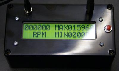
While we have had a suitable large display with backlight for the tachometer for some time, finishing off the assembly notes and actually building a demo model has been delayed. A sudden flush of orders has prompted completion of the necessary bits, and boxes, displays and cable assemblies are now in stock.
 |
 |
Mounting the assembly into the case is done from the front panel, rather than building it into the back of the case as is done with the smaller display. Fore extra security, an additional hole can be drilled in the LCD pcb to hold the opposite end of the electronics. This is optional since the two mountings on the left would be strong enough to hold the boards, and simply securing the right hand spacer to the electronics is probably enough. The assembly sequence is to fit the 12mm spacers to the electronics using 20mm screws on the left, and a 6mm screw on the right. The 10mm spacers are then used to secure the electronics to the display before wiring the two together. The remaining 10mm spacers are then installed on the other end of the display, and these four spacers can then be secured from the front of the box.
The boxes are supplied without holes for the connectors and switch since the positioning of these in the box will be a matter of choice. Mounting them in the front panel is convenient for demo purposes, but the side or back may be more practical depending on how the module is going to be mounted. Since the Maximum/Minimum mode is optional, the switch may not be required.
 |
The only modification required to the wiring over the basic assembly notes is the addition of a couple of extra links when installing the wires between the display and the PCB. Conveniently the backlight simply requires +5V and no provision has been made to change the backlight intensity, so it is simply a matter of providing connections to the backlight from the 5V supply. This is easily achieved directly on the display, with pin 1 looping direct to pin 15 which is adjacent, and pin 2 looping over the top of pins 1&15 to pin 16 as shown in the picture.
The display area is 98mm by 24mm and the case 150mm by 80mm by 50mm deep. The unit draws around 300mA from a 9V DC power pack, but while the 5V regulator gets warm, it is not necessary to fit a heatsink to it.


