220NcmMotorTermination
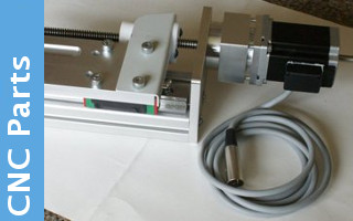
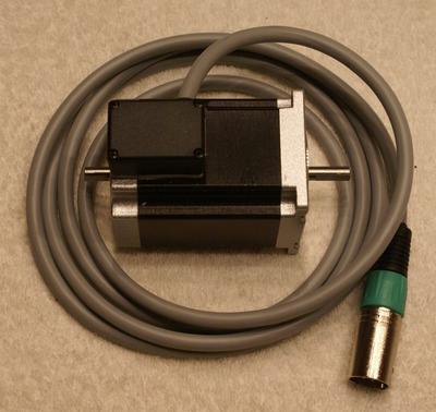
This provides the information for adding a screened 4 way power lead to a stepper motor. The pictures provided are based on the 220Ncm motor normally used with the standard DivisionMaster, but can be adapted to any other motor if required. The 4 pin XLR stryle connector is suitable for use up to 10amps and provides a relaible, locked connection to the driver socket. The cable screen is not connected at the motor end, but should be linked to mechanical earth at the driver end. Motor is configured is series mode giving a 2.1Amp current rating, which is a good match for the 2Amp maximum provided by the standard DivisionMaster
Click on any picture to view a higher resolution version.
![]()
Datasheet on the motor ![]()
The stepper motor comes with flying leads which need to be tidily terminated to prevent accidents and allow easy integration.
![]()
![]()
![]()
Rather then cutting back the rubber seal around the cables, It is better to open up the base hole so that it allows the box to fit snugly against the motor housing. A second 9.5mm in the side provides the entry point for the cable.
A 20mm length of Epoxy Putty is about right to secure the box leaving a neat fillet around the base.
![]()
The cable gland has been removed while the box is fitted to the motor, and then replaced once the epoxy putty has set. (Leave Overnight to cure).
![]()
![]()
![]()
![]()
Cut back about 30mm of sleeve, and un-braid the screen to provide a screen tail. This will not be used, but is left available if it becomes necessary to provide an earth connection to the motor. Normally the screen is only earthed at the plug end. Strip the four wires to provide a 5mm soldered tail to solder the two motor wires to. We are assuming that the motor will be used in parallel mode. Once the tails have been soldered to the wires, a small piece of heat shrink sleeve should be applied to each joint. A cable tie is secured to the cable to act as a strain relief, before the ends are packed into the box, and the lid fitted.
Pin out for cable.
| 1 | Red | connects to motor | Red |
| 2 | Yellow | connects to motor | Black |
| 3 | Green | connects to motor | Green |
| 4 | Blue | connects to motor | White |
| - | connect motor wires together | Blue | Yellow |
| - | connect motor wires together | Orange | Brown |
( Cable colours vary from motor to motor, check the pin out against the supplied data sheet if using a different manufacturer supply )

Plug Assembly
![]()
![]()
![]()
![]()
The other end of the wire is prepared in the same way, ready to be fitted to the plug. The cable clamps need to be fitted to the cable prior to soldering the wires into the plug. The earth tag is connected to the screen tail, and has a short length of tape fitted around it to prevent shorting out to pin 1 or 4.
![]()
![]()
Once soldered, the inner cable clamp is aligned with the rib on the plug prior to sliding into the plug shell. The rib, must align to the groove in the shell for the two to fit, but some force will be required to pass the earth clip into the shell. Once pushed home, the rear cable clamp can be screwed onto the shell securing both cable and plug inner.


