4A Driver - Configuration
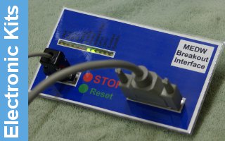
Connection of the 4.2 Amp driver to a MEDW0010 breakout board is relatively simple, just requiring a 4 wire molex link from board, and a four wire connection to the stepper motor.
 The module will run up to 50V, and a
suitable raw supply can be provided by using a 30V transformer. With a
suitable bridge rectifier and capacitorthis will provide around 44V DC which provides a good head room on the 50V capability of the module. The next standard size transformer will be just over the 50V and so risks damaging the module. Also available are 48V PSU modules which as long as they provide a regulated output will also be suitable.
 Molex cable from the MEDW0010 board
pickes up the step and direction signals, and the driver 'Disable'
signal. The modules 'Enable' input is actually a 'Disable' and requires to be driven when the stop signal is used on the breakout board. This is something that many breakout boards do not support.
 Our standard method of
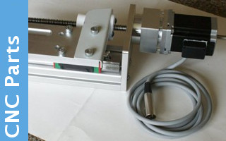
connecting to stepper motors is via a 4 pin XLR style connector which
provides a rating of 6 Amps which is more than adaquate for most of the
smaller motors. The ferrite core offers sufficient EMC screening when
used with a screen cable to the motor itself. See the
motor assembly details for more information
on that. Note that the colour codding on the connection to the board
matches that on the cable.
 The driver module as supplied is set for -ve going step pulses which is not appropriate for the positive pulses we normally use. Jumper 2 inside the module needs moving to closed to provide a more reliable action. While we can configure Mach3 to provide the correct polarity of pulse, this results in 'additional' edges on the step line when the output is disabled and enabled again. With this change, only real step pulses will drive the motor.


