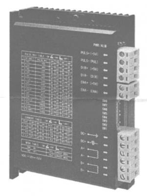
4A Driver - Datasheet
4.2A Stepper Motor Driver ( 160-020-00101 )
Features:
18-50VDC
• 4.2A/Phase (Peak) Max
• 128 Microstep (25600 Steps/Rev) Max.
• Automatic Half Current Option
• All Logic Inputs Isolated
• Full Protection for:
• Over Voltage
• Over Current
• Wrong Phase Wiring
• Low Noise, Low Heat Output
• Single/Dual Clock Option
Specifications:
|
Motor Power Supply |
18-50V DC |
|
|
Current |
4.2A (Peak) Max., 8 settings selectable by dipswitch |
|
|
Current Control |
Pulse width modulation for low ripple current |
|
|
Control Inputs |
5v logic from current sinking (NPN) interface, 15mA typical |
|
|
Microstep |
128 Microstep (25600 steps/rev.) Max. 15 settings selectable by dipswitch |
|
|
Max. Pulse Rate |
300kHz |
|
|
Insulation Resistance |
>500MOhm (at 20° C) |
|
|
Dialectric Strength |
500V AC for 1 minute |
|
|
Normal Operating Conditions |
Temperature |
0° C - +50° C |
|
Humidity |
40% - 80% RH |
|
|
Vibration |
5.9m/s2 Max. |
|
|
Cooling |
Heat Sink |
|
|
Dimensions |
120x90x33mm |
|
|
Weight |
275g |
|
Current Dipswitch Settings:
|
Current Dipswitch |
1.13A |
1.53A |
1.93A |
2.41A |
2.86A |
3.36A |
3.79A |
4.25A |
|
SW1 |
ON |
OFF |
ON |
OFF |
ON |
OFF |
ON |
OFF |
|
SW2 |
ON |
ON |
OFF |
OFF |
ON |
ON |
OFF |
OFF |
|
SW3 |
ON |
ON |
ON |
ON |
OFF |
OFF OFF |
OFF |
|
Microstep Dipswitch Settings (steps/rev.):
|
Steps/Rev Dipswith |
400 |
800 |
1000 |
1600 |
2000 |
3200 |
4000 |
5000 |
6400 |
8000 |
10000 |
12800 |
20000 |
25000 |
25600 |
|
SW5 |
OFF |
ON |
ON |
OFF |
OFF |
ON |
ON |
OFF |
OFF |
ON |
OFF |
ON |
ON |
OFF |
OFF |
|
SW6 |
ON |
OFF |
ON |
OFF |
ON |
ON |
OFF |
OFF |
ON |
ON |
ON |
OFF |
OFF |
OFF |
OFF |
|
SW7 |
ON |
ON |
ON |
ON |
ON |
OFF |
ON |
ON |
OFF |
OFF |
OFF |
OFF |
OFF |
OFF |
OFF |
|
SW8 |
ON |
ON |
OFF |
ON |
OFF |
ON |
OFF |
OFF |
ON |
OFF |
OFF |
ON |
OFF |
OFF |
ON |
Mode Dipswitch Settings:
|
SW4 |
Full Current Mode |
ON |
|
Half Current Mode |
OFF |
Internal Jumpers
|
J1 |
Closed (Default) |
Step + Direction Mode (Single Clock Mode) |
|
Open |
Clockwise + Counter Clockwise Mode (Dual Clock Mode) |
|
|
J2 |
Open (Default) |
Falling Edge of motor pulse |
|
Closed |
Rising Edge of motor pulse |
Input Terminal Details:
|
PULS+(+5v) |
Motor Step on falling edge of pulse (single clock mode (J1=Closed) CW rotation on falling edge of pulse (dual clock mode (J1-Open) Low level of pulse must stand for at least 500ns to ensure reliable response. |
|
PULS-(PUL) |
|
|
DIR+ (+5v) |
High/Low level on this terminal determines the rotation direction of the motor, (single clock mode (J1=Closed)). Direction pulse must be ahead of Step pulse by at least 5us. CCW rotation on rising edge of pulse (dual clock mode (J1=Open)). |
|
DIR-(DIR) |
|
|
ENBL+ (+5v) |
Input 5V on these 2 pins switches power off to the motor (e.g. to enable manual operation). Warning: If the controller is in Microstep mode, the motor drops back to the nearest FULL STEP. Leave disconected if not required. |
|
ENBL- (ENB) |
|
|
Note: Voltages greater than 5V may damage the driver. Use an addtional external resistor if higher control voltages are being used. |
|
Supply Voltage:
18 - 50V DC - Note: The controller will not work below 18V and may be damaged above 50V. Power supply must be smoothed DC with low impedance output.
Automatic Half Current Mode:
When the motor velocity falls below 1rpm, the phase current will drop to 50%. When the motor velocity rises above 1rpm,
the phase current will increase to the rated value. To enable this mode, set SW4 to OFF.
Wiring:
The inputs are totally isolated from the case (ground) and the logic input terminals and can be connected as Common Positive as shown in wiring diagram (or Common Negative if required).
Typical Wiring Diagram
Cooling:
The controller needs to be mounted in a well ventilated enclosure or in a heat conductive sealed enclosure.


