MEDW0010 Construction Guide


The use of resistor packs rather than descrete resistors has allowed the component count to remain quite low. The only thing to take care of is the fitting of some components on the back of the board.
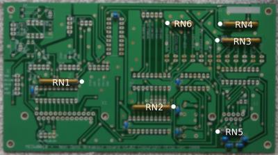
The ten ceramic capacitors and the 6 resistor networks are fitted first. These have been identified to make location easy, and the white dot indicates the end at which the dot on the pack should be located.

The six IC sockets are fitted next. Sockets have been used as it simplifies fault finding if an external fault damages the board. Fit the 20 way, followed by the 18 and then the 14, in that way they should end up in the right locations. The pin 1 ident is to the left on all the horizontal connectors and the top on the PIC socket which runs vertically.

The links and output molexes are fitted next. A ten way stip is provided for the links, but only 9 pins are actually used.

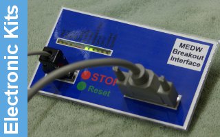
The board has been designed to fit against the front of the controller, so the LED indicators, and the stop and reset switches are fitted to the oposite side to the other components. The long lead of the LED's is fitted to the hole nearest the edge of the board, away from the IC sockets.


The two connectors are fitted to the board with locking jacks and the 5mm spacers, as shown in the small insert. These should be fitted finger tight, and the connectors soldered before tightening fully.

Finally the IC's are fitted. Leave these in the anti static foam until needed, and before fitting hold a well earthed connection to dissipate any static. If your workshop is prone to giving static shocks, then care should be taken to ensure everything is earthed, but normally simple earthing should be all that is required. Only the link by the PIC needs to be fitted to get the board working. The side nearest the PIC should be connected ( need a new picture with it fitted ).
Links
There are four links on the board. Jumpers 3, 4 and 5 allow the spindle speed and fourth axis controls to be linked to alternate outputs if not being used for their main function. The two way link, SV7, allows the output enable to be active even without the computer control. This is needed for test purposes on some systems.
Wiring Options
The motor output connectors have Step, Direction and both polarities of enable. These are provided to allow for drive modules where the motor disable needs to be driven high to disconnect the motor feed, and is active even when the other outputs are disabled.
The fifth five way molex connector provides the two normal output feeds, along with the step and direction outputs from the fourth axis if that is not being used. While the basic outputs are defined spindle and coolant, the collant output may also be used to control a forward/reverse relay as part of the spindle control.
The four way molex allows 5V to be applied to the board, as an alternative to using a feed from the USB connector on the computer. Additionally, 5V can be taken off for other low power accessories. ( Power available will depend on the computers USB capabilities )
9 Way D Socket
- +5V ( Input from USB port or output from board )
- eStop Reset
- eStop Switch
- Spare output if spindle speed is not being used
- Ground
- Input 1 ( Parallel Port Pin 10 )
- Input 2 ( Parallel Port Pin 11 )
- Input 3 ( Parallel Port Pin 12 )
- Input 4 ( Parallel Port Pin 13 )
25 Way D Socket
- Mach3 Charge Pump ( Board will not activate without a stable clock on this pin )
- X Axis Step
- X Axis Direction
- Y Axis Step
- Y Axis Direction
- Z Axis Step
- Z Axis Direction
- A Axis Step ( Can be linked to OP3 if not being used for axis - JP4 )
- A Axis Direction ( Can be linked to OP4 if not being used for axis - JP5 )
- Input 1 ( See Above )
- Input 2 ( See Above )
- Input 3 ( See Above )
- Input 4 ( See Above )
- Spindle Speed ( If isolated Analogue Output stage fitted )
- eStop to Mach3
- Spindle output
- Coolant Output
- to 25. Ground
If the analogue output is not being used, pin 14 can be routed to the 9 Way D, or using a wire link, to one of the spare outputs if they are available.
Analogue Output Option
Since the component pack for this option is a few pounds and not all systems can use it, it has been provided as an option, and the components can be added later if required.

