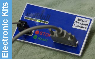
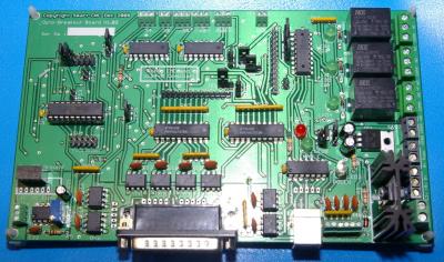
MEDW0011 Opto Breakout Board
Created by: Lester Caine, Last modification: 6 May 2009
- 16 – 85v DC Input power range ( max 200mA at full load )
- Fully opto isolated
- All output signals buffered and controlled by the Charge pump
- Wide operating range – Will work with Mach3 at the 100Khz engine speed and well beyond Step and Direction Outputs for 4 Axes ( X, Y, Z, A )
- Complementary Enable Outputs ( Active High, and Active Low )
- Step, Direction, and Enable Outputs are jumper selectable as 5v or 12v CMOS allowing use with modern ( 5v ) or older ( 12v ) stepper drivers E-Stop Input
- 0 – 10v Spindle Speed Output with isolated 12v DC supply on board
- 3 wire emulation of Spindle speed and direction allowing separate outputs for CW and CCW relays from only the spindle speed and direction pulses
- 3 x Relays rated at 240v, 7A for Spindle Forward, Reverse, and Coolant
- 2 x Open Collector Outputs rated at up to 50v, 100mA each to drive external components ( additional relays )
- 4 x buffered Digital Inputs with input noise filtering
- Onboard Charge pump function ( jumper selectable )
- 5v and 12v Supply Outputs ( 250mA max each ) to drive external boards
- Status LED’s for Power, E-Stop, Enable, and Relay Outputs
- Onboard Microprocessor that controls the Spindle, E-Stop, Charge pump, and Enable functions
- Software can be updated via the onboard ICSP header
- Upgrade path to enable further functionality e.g. LCD / Keypad Pendant, USB connection, Additional inputs and Outputs
- UL 94V0, RoHS, and EMC compliant
Kit prices will follow shortly ...

