Micromill Leadscrew Assembly
The lead screw assembly is fairly simple and requires little maintenance. Regular adjustment of the loading on the lead screw bearings, and of the lead screw nut will maintain a low backlash on each axis.
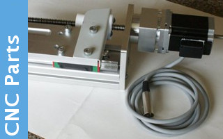
The leadscrew nut has three allen screws built in, the middle one is used to open the nut out, while the outer pair close the nut up. During regular maintenenace all that should be required is loosening the center screw and then tightening the outer two. Quarter turn steps will keep things tidy, but if there is detectable movement in the nut, then large steps may be appropriate. Try and keep tightening of the outer screws even so as to maintain a parallel alignment. It is possible to over tighten one end while leaving the other slightly further open. My preference is to tighten the nut until a point where if you turn the mounting lug horisontal, it slowly drops to vertical. It should not be too tight as this will introduce unnecessary wear.
The one thing that does need to be born in mind is WERE on the leadscrew you carry out this operation. Heavy use of a section of the leadscrew will eventually result in wear, and so the nut will bind at the ends when adjusted correctly in the middle. It is the compromise between accuracy, area of use and cost that will determine whether th lead screw needs replacing. You will see from the pictures on the maintenance page that I've adjusted the nuts near the end of the leadscrew. If I can't run the nuts to the end because of wear, then it will just be a matter of asking 'does the machine use that section of thread?' and if not, then one simply stays within the normal area of use when adjusting. This does cause problems when reassembling, but there may well still be another couple of years of use available simply because the site never goes outside a smaller work area.
The loading of the bearings on the leadscrew require a little less attention than the nut. You will see from the picture that there are a pair of bearings, and the wire ring is used to maintain a small gap between them. The nut is tightened to maintain pressure betweeen the two bearings, which will obviously wear on their inner faces with use. I have in the past swapped the two over during a maintenance visit much like swapping the tyres on a car to even wear, and while the beraings will be a little looser, this does seem a sensible move while the machine is apart. One can normally feel when the bearings need replacing, and this was the case with both the y and z axis on the current overhaul. The z axis had a significant 'detent' when rotating the leadscrew, while thg y axis just felt enerally rough. With a new asembly one can freely rotate the bearing housing on the lead screw, and I opt for tightening the nut until the housing will do a couple of rotations before stopping. If it is too loose it will continue spinning for some time, but again one gets a feel for what is right, and normally a quarter or half turn is all that is required during a maintenance session.
If it is necessary to replace the leadscrew or change the bearings there are a few things to watch out for. The first one is the key on the shaft which holds the graduated ding and the coupling body. When taking the assembly apart, the nut is removed, and then the coupling and graduated disk are slid off the shaft. With luck these will not be stuck, but you may need to apply some pressure to move them. Resting the body of the bearing housing on a vise, and gently tapping the leadscrew through is the safest aproach but keep a hand on the leadscrew to prevent it dropping out when the seal is broken. It will NOT go right through in ny case, since the 'D' key will stop at the bearing spacer. The key is a tight press fit into the slot, and removing it may be a problem. A gentle tap with a sharp chisel should just move it, but I've also resorted to simply filling it down since the lead screw is scrap anyway. Once clear, the leadscrew can be slid out of the housing.
I'll add some notes on replacing the bearings later ...
Reassembly is relatively straight forward. Only thing to remember is to fit the space washer that goes at the end of the bearings BEFORE applying the 'D' key! Can be a pig getting it out again whenyou forget ... A new lead screw will come with a 'D' key taped to it, so there is no need to worry about the old one. Fitting the key can be a little bit of a fiddle, but once started, a pair of pliers should be used to press it fully home. Until it is, it will not fit through the slots in the graduated disk and the coupling. It may be necessary to apply some pressure to get the body of the graduated dial over the key, but make sure that the key is correctly lighned with the slot, and is at least starting to go in before applying any pressure. Once the dial is on, the coupling normally simply slides on after. I wrap a bit of paper towel around the coupling and clamp it with a pair of grips while tightening the nut. Being a nyloc nut, it should be replaced rather than reused.
One tool that can be useful at this point is an electric screw driver. This can be used to manually run the lead screw nut along the thread to check for tight spots. Alternatively the stepper motor can be dropped back on and used for the same purpose.


