Step and Direction board Installation
Step and Direction to Phase Conversion Board for the MicroProto Systems Driver System
Copyright Kurt Daley - MicroProto Systems - 2004
Adapter Board Installation
The adapter board allows the MicroProto Systems step motor driver system to convert standard Step and Direction signals into the phase sequence signals used to drive step motors. This also allows full 4 axis control from a single printer port. In addition 2 output signals and 5 input signals are available to the user. Installing the adapter board is a simple procedure that only requires changing a few cables. The procedure is outlined below.
Adapter Board Installation Steps:
- Remove 120 VAC power cord from driver box.
- Open up the driver box by removing the black cover lid.
- Unscrew the Printer Port Connector from the back panel of the box shown in Fig. 2. If you have a 4 axis driver box unscrew the second Printer Port Connector also.
- Unscrew the 4 (2 on panel) screws holding the upper circuit board.
- Remove the large ribbon cable from the bottom circuit board.
- Reach under the upper circuit board and remove the small ribbon cable attaching the upper circuit board to the lower circuit board shown in Fig. 3.
- Attach the new large cable to the bottom circuit board with the red cable line facing away from you or toward the capacitor side of the driver box.
- Screw the upper circuit board back into place.
- Remove the two 4-40 Jack Screws from the adapter board Printer Connector and insert the connector into the panel cutout as shown in Fig. 4.
- For 3-axis driver systems with a Z-axis driver board attach the 10 and 25 conductor ribbon cables as shown in Figs. 4, 5, and 6.
- For 4-axis driver systems attach the short and long 25 conductor ribbon cables as shown in Figs. 4 and 7.
- Slightly unscrew the 2 terminals of the large blue capacitor and attach the power input cables as shown in Fig. 8. The Red wire connects to the positive terminal with the Blue wires connected to it.
- Plug power input connector into small 3 pin terminal on adapter board.
- Attach black cover lid.
- The Parallel Printer Port Pinouts detailed on the Microproto SD Printer Port Pinout.
- The pin connections for the Microproto SD 8 pin Din Port Pinout and the corresponding Molex housing connector are shown in Fig. 9.
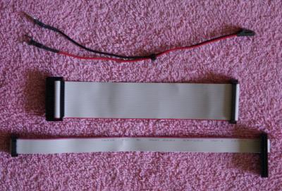
Fig. 1- Supplied cable set Cable set supplied with kit.
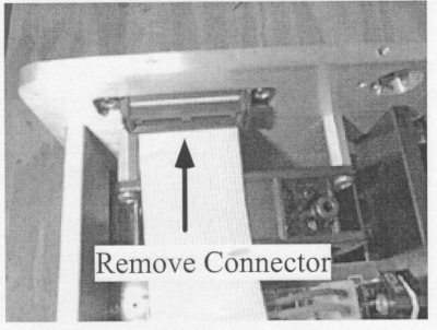
Fig. 2- Removal of standard printer cable in box.

Fig. 3 - Bottom circuit board showing removal of small ribbon cable and addition of new ribbon cable.

Fig. 4 - Top view of adapter board showing placement of printer connector and ribbon cables.

Fig. 5 - Attachment of 25 and 10 conductor ribbon cable connectors on adapter board for 3-axis driver systems.

Fig. 6 - Connecting the 10 pin ribbon cable to the bottom header connector on the Z axis drive board.

Fig. 7 - Installation of Adapter board showing placement of ribbon cables for a driver box containing 4-axis driver boards.

Fig. 8 - Installation of power input cables to adapter board. Attach Red to Blue and Black to Black on large capacitor terminals.

