DRO Tacho Buffer
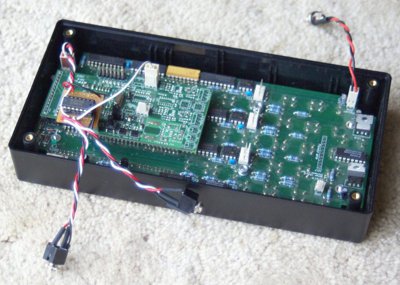
Having been using the same reflective and slotted sensors with the DRO350 and the Tacho, it was somewhat surprising that they did not seem to be working reliably with the DPU. The first part of the jigsaw would seem to be that the power supply to the additional sockets on the lite version of the DPU do not like beening loaded too heavily, and are not giving a clean +5V supply. This is solved by using the older 'Aux' input which is powered directly from the DRO350 power supply. Once the stability of the power supply was sorted, this still left a problem with the input signal not providing a clean switch. Scott has pointed out that these inputs have the pull-up enabled on the ARM processor, but that is to +3.3V and seems to be the main source of the problems. The various open collector sensors I have tested do not like this pull-up, and trying to add additional pull-up to the 3.3V supply has the same problem as powering the outputs from the DPU. The easiest fix has been simply to fit a buffer chip running from the 5V supply, which then works identically to the DRO350 as far as inputs are concerned.
Circuit diagram will follow shortly, but It is not worth having a PCB made for this although I may add a module to the next run of Tacho PCB's
The DRO550 with it's internal power planes does not have a problem with the power to the sockets, but still exhibits the same problem with the input signal. Up to 6 channels can be processed through the 74HCT14, so making up a 4 channel version for the DRO550 is next on the cards.


