MEDW0010 Breakout Board
 Shopping Basket of parts
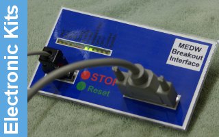
The MEDW0010 Breakout Board is designed to provide a clean interface between any parallel port and the CNC hardware. It is designed in particular to handle the lower power levels of the ITX computers used for Mach-in-a-box, but is suitable for use with any computer. Safety is provided by an interlocked E-stop circuit linked to the Mach3 charge pump. External E-stop switches can be added to trip the output drivers and Mach3, but this lockout has to be reset on the board before Mach3 will continue.


The board provides outputs for four step and direction channels, or the fourth channel can be used for additional external relays. Two additional outputs are provided on the basic build, and an optional isolated analogue output can be fitted for use with these output to provide full spindle control. The board is intended to be powered via 5V from the USB port of the computer, or alternatively an additional 5V supply can be used. In order to prevent any possible problem with handling switched mains feeds, the board is intended for use with external solid state relays, which are the preferred route, but will drive conventional relays if an additional power supply is available. LED's are provided on these outputs, and on the fourth step and direction channel relay outputs, which can then also be used to check step and direction operation. Providing LED's on all channels was felt to be overkill, and could distract from the more important LED's.
- 4 off Step and direction outputs are buffered by a 74HCT573, which provides a 35mA 5V drive from 2 to 5Volt input signal
X - 2=Step, 3=Dir, Y - 4=Step, 5=Dir, Z - 6=Step, 7=Dir, A - 8=Step, 9=Dir - Both active high and active low enable signals are provided - useful for drivers that have a +ve disable signal.
- 4 off 0.5A open collector outputs - 16 - Spindle, 17 Coolant ( or Direction )
Two shared with A axis step and direction so not available when 4th axis is in use, otherwise 8 and 9 can be used as extra outputs. - These outputs can handle up to 50V, so 24V or 48V relays can be driven ( needs an external PSU for this voltage )
- Opto-isolated analogue output providing Isolated +12V and 50mA, 0 to 10V variable signal ( pin 14 from outputs )
- Mach3 charge pump required to enable outputs ( pin 1 from outputs )
- Interlocked eStop provided back to Mach3 ( pin 15 to inputs )
- Four spare inputs buffered via 74HCT573 ( Inputs 10 to 13 )
A 9 way 'D' connector provides external access to the four spare digital inputs and allows an external E-stop and reset button to be connected. An E-stop button adjacent to the machine should be concidered a must have, and we would suggest that this option is taken up by customers. While no opto isolation is provided on these inputs, an internal buffer protects the computer feed. The 5V supply is also available if required to power slotted sensor limit switches.
Kitting sheet is completed, and the construction guide is also available.

Outputs from the step and direction channels are provided by pin headers, and pre-assembled cables will be available to use with these and are supplied as standard with the stepper motor kits. Because of the diferences between stepper drivers, both polarities of enable signal are provided on the header, so that the correct 'disabled' signal can be used with the driver to disable them.
 Connecting to Arc Euro 4.2Amp Chinese driver Connecting to 3Amp Drivers
CAUTION - Mach3 can be configured to provide the charge pump signal output even while it is in E-Stop. THIS is NOT recommended from a safety point of view, and care should be taken to ensure that a charge pump signal is only provided when Mach3 has been set active!


