Micromill Maintenance
Since taking over support for the CNC Taig machines in the UK I've serviced a number and am now getting quite used to deciding what needs doing to a machine. Normally this is done on site, so documenting the procedure is normally a little difficult, but the latest machine has come back to base while my demo machine replaces it on site. The customer has been having problems with the accuracy of text, so at 6 years old it was decided that a full overhaul was in order. I will not show the state of the machine when it arrived, it was not one of the worse I've seen, but a lot of swarf had been left at the site. The machine has always been kept well oiled and this reflects in the state of it after stripping down.
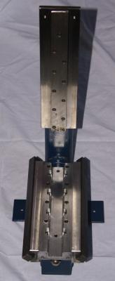
Parts have been washed and wiped as dismanting proceeded, and the base is striped down to the level seen above. A good cleaning of all of the surfaces has been undertaken, and all of the bearing surfaces have been given a clean wih degreaser and 0000 grade wire wool. There is no obvious problems visible to these areas, andthe machine is ready for reassembly.

The main area for attention is the leadscrews, and the three from this machine were in various states of concern. The machine had been fitted with new nuts 3 years ago, and had been adjusted twice since, but both the X and Y thread now had a noticable tighness near the ends of the thread. The machine does 98% of its work within the centre 75mm square so this is to be expected. However what was not expected was the state of the bearings on the Y axis, which had a noticable 'steppyness' when rotating manually. This was not noticed while on the machine as it was similar to that introduced by the stepper motor. With the close loop motors it is impossible to manually move the axis, but even where the knobs are accessible, the best way of assessing things is with the motor off.
The z axis lead screw had fairly even wear since jobs have a range of heights and so the whole range gets used quite regularly. What had been a problem with the z axis however was that it was sticking from time to time. Initially this was put down to the spindle motor overheating, and after a few hours of cutting, this had actually been causing the z axis to jam solid. The original spindle has been replaced with a Kress spindle, which has also improved the quality of the results conciderably, but the z axis was still rough when turned manually. Once dismantled, the source of the problem was obvious, with a very distinct detent in the rotation of the bearings.
In this case we have simply replaced all three axises with new lead screw assemblies, but the lead screw assemblies can easily be reconditioned on site. Check out the Leadscrew assembly notes for details on how to do this.
Once we have either adjusted, or reconditioned the lead screw assebmlies, the mill can be rebuilt. Having the base out of it's cabinet makes life easier, since one can turn the bed on it's back and get at the allen bolts in the bottom of the Y axis. Since all of the oil has been removed from the components, it is appropriate to replace this liberally as assembly proceeds.


I like to assemble the base, but leave the stepper motor mount loose so I can check the adjustment of the y axis jib strip by hand. The nut from the lead screw is fitted, and then the right hand v groove is lined up with the bed runner, and the whole assembly droped down onto the base. At this point the left hand jib strip can be slipped in from the front, and the clamping plate offered up. While holding the plate in place the whole machine can be roocked to it's back, and the three bolts fitted. Do not tighten these fully at this stage as the job strip needs room to move while being adjusted. I tend to tihten up the adjusting screws until the y axis is getting difficult to move, then tightening the lock nuts normally introduces enough slack to allow free movement. You should be able to slide the y axis smoothly by hand with no disernable movement from side to side. Once one is happy whith this movement, the clamp plate can be tighted up.

The lead screw can now be mounted, but do not tighten this fully until the table can be moved to the front edge. This is easiest to do with the stepper motors. The spacer seen in the pictures gives an extra 25mm of movement on the y axis, and the Kress spindle mount also move the spindle 25mm forward.


Assembling the bed is carried out in much the same way as the y axis cradle, but all that needs to be adjusted is the x axis jib strip along the front of the bed. The adjusting bolts at either end allow the tapered section to be tightened and lossened. It is a matter of feel, but the table should move smoothly by hand. By sliding the table from end to end manually one can feel how it is moving. With the table at one end, one can hold the base, and try moving the table back and forwards. Once one is close to a good fit, there will be no detectable movement in the end of the table.
It is convenient at this point to refit the stepper motors and finish adjusting and tightening the bed assembly, however the z axis can be reassembled prior to doing that if you wish.


The z axis has four bearing surfaces. The vertical stability is provided by the strip on the front of the column, which has a similar tapered adjustment as the x axis. Normally I will adjust this even before fitting the leadscrew, and then check it when the leadscrew is in place. The head is retained to the column with the two right angle clamps which hook around the back of the column plate. It is normally adaquate to hold the front and back parts tight together while tightening the side nolts, but once assembled there should be no disernable raocking action front to back. This is easier to check with either the spindle or in our case the mounting plate in place. Again once one is happy with the feel of the movement by hand, the lead screw can be clamped in place.

Final checks are carried out by jogging the axises around using the stepper motors. All three axis should move smothly from end to end without any detectible judder. The leadscrew clamp should only be finally tigthened up once the axis is fully against the motor end. This ensures that therlead scew is in the right place at it's tightest point.
Once one is happy with the general performance there are a couple of further checks that need to be carried out before one is finished.The spindle needs checking for squareness to the table, and the actual backlash for each axis needs to be measured and updated within Mach3.
If the backlash still seems a little high, and anything over 0.25mm is probably excessive, then it may be necessary to dismantle that axis again and check the adjustment of the lead screw nut.
it is possible to remove the y axis assembly completely in order to readjust that nut without touching the x axis setting. 
Links to further articles on Maintenance of the Taig Mill can be found here.

